Hand-Motion-Controlled Doodle Jump Game on FPGA
System Verilog / FPGA
In collaboration with 張家翔、李允恩.
This is the final project of Digital Circuit Lab (Fall 2021).
Introduction
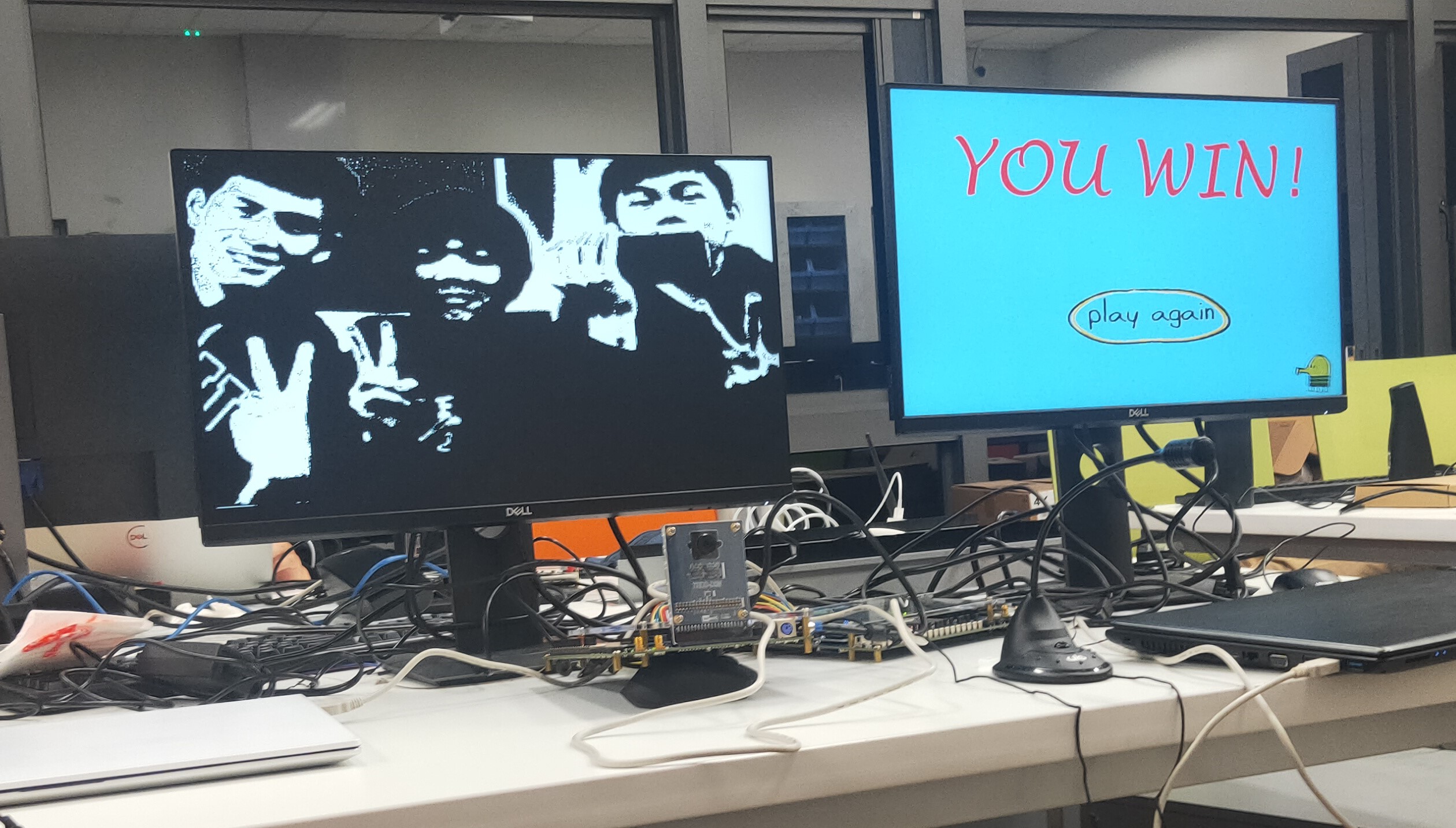
This is a Doodle Jump Game without the need of touching the screen! The game is started by inputting a loud enough sound (You can yell “START!” or “LET”S GO”). The avatar’s movement in the game is controlled by moving your hand left or right in front of the camera. The avatar can shoot bullets if player opens and clench his/her fist.
The whole design consists of two FPGA boards one camera, one mic, and two screens. The first FPGA, Motion Detection FPGA, deals with the image processing of user’s hand and the voice processing of user’s sound to retrieve the instruction of the user. The second FPGA, Game FPGA, controls the procedure of Doodle Jump game.

See the demo video below!
Implementation Details
Motion Detection FPGA
Block Diagram
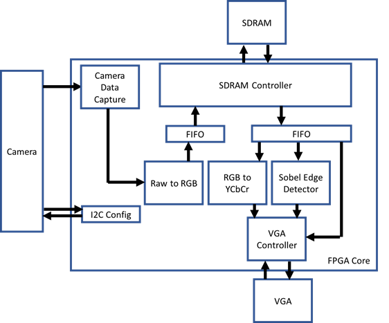
The raw data from the camera will first be stored into SDRAM in RGB format. These data are then fetched out, converted to YCbCr for game signal processing.
Hand Position Detection (for moving left or right)
We use color recognition to detect the position of the hand in the image. To better filter out the skin color from the image, we convert the RGB image data format to the YCbCr color space, eliminating the influence of brightness. Based on test results, we define pixels with 91 <= Cb < 112 and 133 <= Cr < 180 as skin color. To facilitate hardware calculations, we amplify the equations by 1024, resulting in:
Y = [(263 * R) + (516 * G) + (100 * B) + 16777216] >> 10
Cr = [(450 * R) - (377 * G) - (731 * B) + 134217728] >> 10
Cb = [- (152 * R) - (299 * G) + (450 * B) + 134217728] >> 10

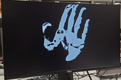
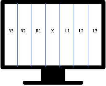
To determine the left or right position of the hand, we divide the screen into seven equal parts and calculate the number of skin-colored pixels in each segment. We select the segment with the highest number of pixels. If the number of pixels in that segment is greater than a predefined threshold, we send the corresponding movement signal to the game control FPGA board. The mapping of the control signals is as follows:
X: Stay in place
R1: Move to the right (slow)
R2: Move to the right (medium)
R3: Move to the right (fast)
L1: Move to the left (slow)
L2: Move to the left (medium)
L3: Move to the left (fast)
Gesture Detection (for firing bullets)
Accurate gesture recognition often requires complex computing. Fortunately, in our case, we only need to distinguish between two gestures (open fist and clenched fist) for bullet firing, which hugely simplifies the process. We have observed that clenching the fist leads to more pronounced hand contours. Therefore, we utilize edge detection techniques to differentiate between these two gestures.
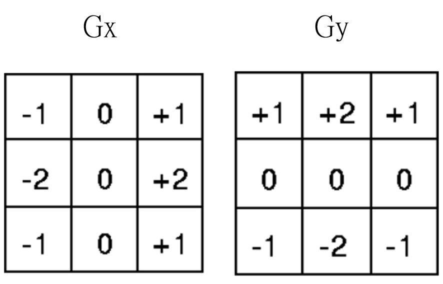
First, we convolve the image with Sobel filters in the x and y directions. Then, we calculate the absolute sum of the resulting values.To have access to the data from the previous two rows at the current moment, we utilize a line buffer with a length of 800. The VGA’s read signal is used as the Clock Enable signal to store the data. The hardware circuit design method is shown in the middle figure below:

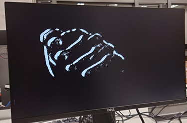
After performing the Sobel edge operation, three post-processing steps are performed:
- Binarization: Convert pixels to either black or white based on their relationship with a threshold value. The player can use the FPGA switch (SW) to set the threshold value.
- Skin Color Filtering: To prevent the detection of non-hand edges, we remove all non-skin-colored edges. This step significantly improves the tolerance towards the background.
- Purefication and Noise Reduction: For each pixel, if its surrounding pixels are all non-edge points, we also consider it as a non-edge point. This process reduces noise in the image, resulting in more precise calculation of hand edges.
Sound Detection (for starting the game)
Before the game starts, we utilize the microphone for audio input. If the received sound level in decibels (dB) exceeds a certain threshold (set to the volume of normal speech), we transmit the game start signal to the main game program. The detailed principle is as follows:
After I2C initialization, we start receiving audio data through I2S. In the WM8731 16-bit Audio Input, bits [14:10] represent the volume level information, ranging from 11111 for +12dB to 00000 for -34.5dB. We can thus find an appropriate threshold that triggers the control signal when aligned with speaking into the microphone based on experimentation.
Furthermore, as it is difficult to control the number of cycles in which the human voice will persist, each time a “high decibel sound” is detected, we pull the game start signal high for two cycles (accounting for the I2S and main game clock differences), then pull it down to 0 and maintain this state for approximately 1 second. Only after this time, we can respond to external sound levels again. This design aims to avoid the problem of multiple game start signals triggered by a single sound occurrence.
Game FPGA
Block Diagram
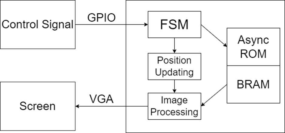
Game Image Processing
For the image processing part of the game, we have designed it based on similar projects found on the internet. Here are the details:
Image Storage: Each image is divided into two files. The first file represents the mapping of colors and their corresponding indices, as shown in the example below:

This file indicates that color CCC corresponds to index 0, color AAA corresponds to index 1, and so on. The color representation uses 12 bits RGB, with the color order being R, G, B. For example, 874 represents red 8, green 7, and blue 4.
The second file represents the mapping of pixels in the image to color indices, as shown below:
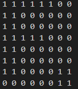
This file indicates that the colors of the first 1-6 pixels correspond to index 1, and the colors of the 7th and 8th pixels correspond to index 0, and so on. By referring to the color data in the first file, we can determine the color of each pixel.
Image Loading: In the program, we use two types of memory: ROM and BRAM. Since the number of colors in the color mapping is small (less than 16), we use an asynchronous ROM for access. Each value in the second file represents the data of one pixel, and these data are sequential. In VGA display, each cycle processes and outputs the data of one pixel. Hence, we use block RAM (BRAM) in the FPGA for data access, reducing resource consumption and latency.
Image Display: In each cycle, the program checks if the position of the pixel to be displayed in that cycle overlaps with the positions of the various images. Based on the order of image display, it determines which image should be displayed for that pixel. If there is no overlap between the position of each image and the pixel, the background is displayed instead. Once the image to be displayed is determined, the program uses the ROM and BRAM to read the color index and its corresponding color for that pixel. It then converts it into the 24-bit RGB format that can be displayed by VGA for VGA output.
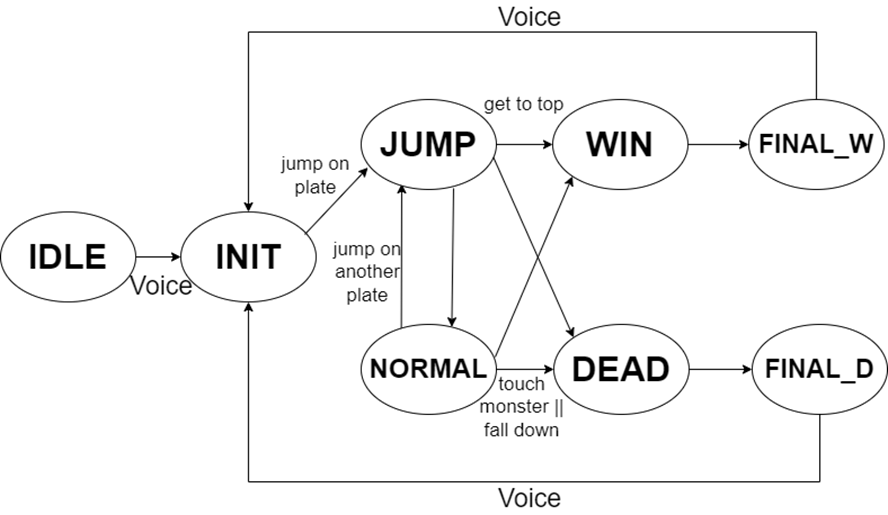
The VGA output format used in this game is 640x480. For a frame, there are a total of 800 cycles horizontally and 525 cycles vertically, including the default synchronization signals. At the beginning of each frame, based on the current game state, the program calculates the positions of each image and determines the new game state to obtain the correct image coordinates for that frame.
Random Level Design
We aim to provide players with a different experience each time they enter the game, with varying positions of platforms and monsters to increase the game’s diversity and enjoyment. To generate random positions for platforms and monsters, we predefine the coordinates of 1000 platforms and 20 monsters. Then, using an LFSR (Linear-Feedback Shift Register), we generate a random sequence. The appearance positions of platforms and monsters on the screen are determined based on this sequence.
Presentation Slide
🌸 Photo Dump 🌸
